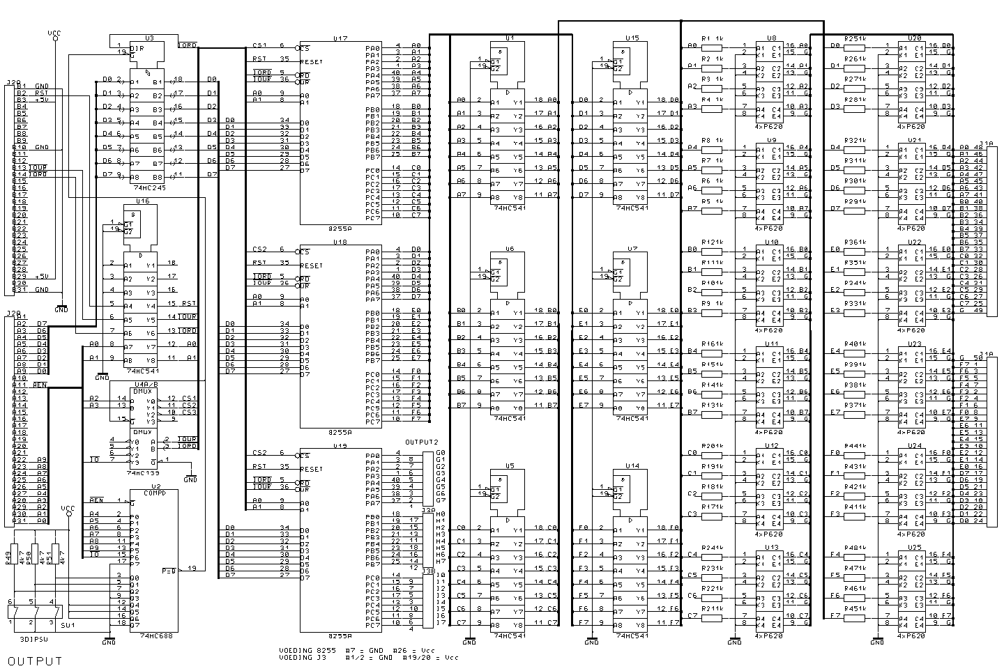
CompuTrein ISA output card
The output card is designed around three 8255A PPI's
(Programmable Peripheral Interface, see 8255 datasheet, opens in new browser window if you have
Adobe Acrobat Reader version 3 or up installed). Each
8255 has 24 programmable inputs/outputs. The CompuTrein
program uses 48 outputs, this means that 16
inputs/outputs are available for later expansion. All 48
outputs are buffered and electrically decoupled by
optocouplers.Address Selection
The address
selection of the 8255's (U17..19) is created with a 8-bit
comparator (U2) and a de-multiplexer (U4a). A0 and A1 are
buffered by U16 and are led to the A0 and A1 inputs of
the 8255's to select one of the 4 registers in a 8255
(see 8255 datasheet). The de-multiplexer (U4a) uses A2
and A3 to select one of the 8255's. The outputs of U4a
are connected to the Chip Select (CS) inputs of the
8255's. The 8-bit comparator U2 uses the address lines A4
to A9 and the IO signal to activate the de-multiplexer
(the IO signal is active as long as IORD or IOWR is
active, U4b). The de-multiplexer is only activated if the
Address Enable (AEN) signal from the ISA bus is low
(address on the bus is available). The comparator output
is low when the inputs P0..7 are equal to the inputs
Q0..7 (P=Q). If this output is low it activates the
de-multiplexer which selects one of the 8255's.
The state of the Q0..2 inputs of the comparator U2 is
selectable by means of the dil-switch SW1. In this way
the start address of the output card can be selected. If
necessary more than one output card can be mounted in one
PC as long as they all have a different starting address
and the addresses do not conflict any other device in the
computer. The selectable addresses are shown in the table
below.
|
SWITCH SW1 |
8255A U17 |
8255A U18 |
8255A U19 |
| 1-6 |
2-5 |
3-4 |
PA |
PB |
PC |
CTRL |
PA |
PB |
PC |
CTRL |
PA |
PB |
PC |
CTRL |
| ON |
ON |
ON |
300h |
301h |
302h |
303h |
304h |
305h |
306h |
307h |
308h |
309h |
30Ah |
30Bh |
| ON |
ON |
OFF |
310h |
311h |
312h |
313h |
314h |
315h |
316h |
317h |
318h |
319h |
31Ah |
31Bh |
| ON |
OFF |
ON |
320h |
321h |
322h |
323h |
324h |
325h |
326h |
327h |
328h |
329h |
32Ah |
32Bh |
| ON |
OFF |
OFF |
330h |
331h |
332h |
333h |
334h |
335h |
336h |
337h |
338h |
339h |
33Ah |
33Bh |
| OFF |
ON |
ON |
340h |
341h |
342h |
343h |
344h |
345h |
346h |
347h |
348h |
349h |
34Ah |
34Bh |
| OFF |
ON |
OFF |
350h |
351h |
352h |
353h |
354h |
355h |
356h |
357h |
358h |
359h |
35Ah |
35Bh |
| OFF |
OFF |
ON |
360h |
361h |
362h |
363h |
364h |
365h |
366h |
367h |
368h |
69h |
36Ah |
36Bh |
| OFF |
OFF |
OFF |
370h |
371h |
372h |
373h |
374h |
375h |
376h |
377h |
378h |
379h |
37Ah |
37Bh |
Databus
The data
lines of the ISA bus are buffered with bi-directional
ports which are activated by the address selection. The
direction of the ports is depending on the IORD signal
from the ISA bus. The data lines are connected to the
data bus of the all three 8255's.
Reset
The RST
signal of the ISA bus is buffered in U16 and connected to
the RESET input of the 8255's. If the reset goes high the
8255's are set to their initial state.
Outputs
The outputs
of the 8255's U17 and U18 are buffered by U1, U5..7, U14
and U15. The selection inputs G1 and G2 are connected to
ground. The outputs of the buffers are connected through
a resistor to the optocouplers U8..13 and U20..25 (each
block consists out of 4 optocouplers). The transistors of
the optocouplers are used as an open-collector output
which are available on connector J1 at the rear of the computer. The
inputs/outputs of the 8255 U19 are available
on connector J3 (inside computer) for later expansion.
Schematic
|